Why Choose DIN 42530 1/250 Transformer Bushing?
Choosing the right transformer bushing is a small decision with serious operational consequences. The Din 42530 1/250 Transformer Bushing is designed for transformer connections rated at 1 kV and 250 A. Its standardized dimensions support practical replacement, consistent installation, and easier maintenance planning.
CIGRE Technical Brochure 642, Transformer Bushing Reliability, identifies bushings as critical components in transformer service. The report emphasizes insulation condition, sealing performance, electrical stress, and installation quality. These factors matter beside the nameplate. A clean porcelain surface, correctly tightened terminal, and intact gasket can prevent avoidable heating and moisture entry.
Dr. Thomas K. Saha, a recognized transformer-diagnostics specialist, states, “A bushing should be assessed as part of the transformer, not in isolation.” This principle supports a careful selection process. The bushing must match the transformer’s voltage, current, mounting arrangement, conductor size, and environmental conditions.
The IEC 60137 standard also highlights the importance of insulation coordination and reliable terminal performance for alternating-current bushings. Meanwhile, IEEE C57.19.00 provides general requirements for transformer and reactor bushings. These references give engineers a stronger technical basis than price comparison alone.
Still, a standard designation is not a complete guarantee. It does not compensate for poor storage, incorrect torque, vibration, or contaminated insulation. That is the uncomfortable part. Field conditions can defeat a theoretically suitable component.
For many conventional transformer installations, the Din 42530 1/250 Transformer Bushing offers a sensible balance between compatibility, availability, and serviceability. Its value depends on verification. Check every dimension. Record the installation details. Then confirm performance through documented inspection and testing.
What Is a DIN 42530 1/250 Transformer Bushing?
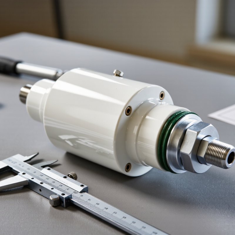
A DIN 42530 1/250 transformer bushing is a standardized low-voltage connection component. It allows a conductor to pass safely through a transformer tank wall. The “1” commonly refers to a 1 kV rated voltage class. The “250” indicates a rated current of 250 A. In practical installations, the bushing combines electrical insulation, mechanical support, and a sealed passage through the tank.
Its design usually includes an insulated body, a conductive terminal, mounting hardware, and sealing elements. The bushing must withstand operating voltage, continuous current, temperature changes, and oil contact when used with an oil-filled transformer. Correct tightening matters. Excessive force may damage the insulator or gasket. Insufficient force may cause leakage, looseness, or overheating at the connection point.
Technicians should check the transformer drawing, conductor size, terminal arrangement, and required creepage distance before ordering. DIN references can be misunderstood when older equipment is modified. The marking alone may not confirm every dimensional detail. That assumption can be wrong. During installation, inspect the insulating surface for cracks, keep contact areas clean, and verify torque with calibrated tools. A resistance check and insulation test can reveal poor connections before energization. Field conditions sometimes expose problems that catalog data does not show, especially with vibration, thermal cycling, or aged seals.
How the 250 A Rating Supports Transformer Current Transfer
Why Choose DIN 42530 1/250 Transformer Bushing?
A DIN 42530 1/250 transformer bushing provides a defined path for current transfer. Its 250 A rating supports continuous current movement between the winding and external connection. This capacity helps reduce unnecessary heating at the connection point. In field inspections, loose contacts often create more heat than expected. That matters.
The current passes through the conductor, contact surfaces, and terminal hardware. Each area must handle electrical and mechanical stress. A correctly selected 250 A bushing can support stable operation when the transformer load remains within its design limits.
Its standard dimensions also help technicians verify fit, clearance, and connection alignment before installation. Small alignment errors can increase contact resistance.
The rating alone is not a complete selection guide. Ambient temperature, enclosure ventilation, conductor size, duty cycle, and installation torque can change performance. A catalog value may look reassuring, but actual service conditions are less tidy. I would not select this bushing from amperage alone. Inspectors should confirm the transformer’s operating current, connection arrangement, insulation requirements, and applicable technical documentation. Periodic checks can reveal discoloration, looseness, or unusual temperature rise before a minor connection issue becomes a serious operating concern.
DIN 42530 Insulation Requirements for 50/60 Hz Operation
Choosing a DIN 42530 1/250 transformer bushing begins with its insulation behavior at 50/60 Hz. These frequencies create continuous electrical stress inside the transformer. The bushing must maintain stable insulation under normal voltage, temperature, and moisture conditions. Its porcelain or insulating body should resist surface tracking and internal breakdown. Small defects can become serious after years of thermal cycling.
The 1/250 designation should never be read alone. Confirm the rated voltage, current, creepage distance, and required power-frequency withstand level from the applicable DIN documentation. Insulation coordination also depends on the transformer’s system voltage and installation environment. A coastal substation may need more creepage than an indoor, dry room. Dust matters too. During inspection, technicians should check cracks, chips, loose hardware, and contamination around the flange and terminal.
At 50/60 Hz, testing commonly focuses on power-frequency withstand performance and insulation resistance. Test conditions must follow the relevant standard and project specification. Field measurements are useful, but they cannot replace a complete design review. I have seen specifications that matched mechanically but missed the required clearance. That mistake is easy to overlook. It deserves a second check before procurement. Verify drawings, sealing details, conductor dimensions, and earthing arrangements before installation.
DIN 42530 1/250 Compared with IEC 60137 Bushing Practices
Why Choose DIN 42530 1/250 Transformer Bushing?
A DIN 42530 1/250 transformer bushing is often selected for its familiar mechanical format. The 1/250 designation commonly indicates a 1 kV class and 250 A rated current. However, project documents must confirm this interpretation. Dimensions, conductor size, mounting holes, and sealing details can vary by design.
DIN 42530 mainly supports dimensional and application consistency. IEC 60137 takes a broader performance approach for insulated bushings above 1 kV. It addresses insulation coordination, temperature rise, dielectric tests, partial discharge, and impulse withstand. Therefore, a DIN-based bushing should not be called IEC-compliant only because its voltage and current ratings appear similar. The test evidence matters.
During replacement work, I would check the terminal height first. A few millimeters can affect busbar alignment. I would also inspect the gasket surface, creepage distance, clearances, and oil-side connection. These details are easy to overlook. They can create heat spots, leakage paths, or installation stress.
The practical advantage of the DIN 42530 1/250 format is predictable mechanical integration. The limitation is equally important.
It may not provide the complete verification record expected under IEC 60137 practices. A careful specification should request drawings, routine test results, dielectric data, and operating-temperature limits.
In some installations, the existing transformer design may require a higher impulse level or a different sealing arrangement. That is where a simple dimensional match becomes an incomplete engineering decision.